Cmos gate logic voltage nand gates not current ground does reference (a) what are logic gates?(b) draw a circuit diagram for dual-input and Logic gates instrumentation tools
Current and Voltage in CMOS Logic Gate - Electrical Engineering Stack
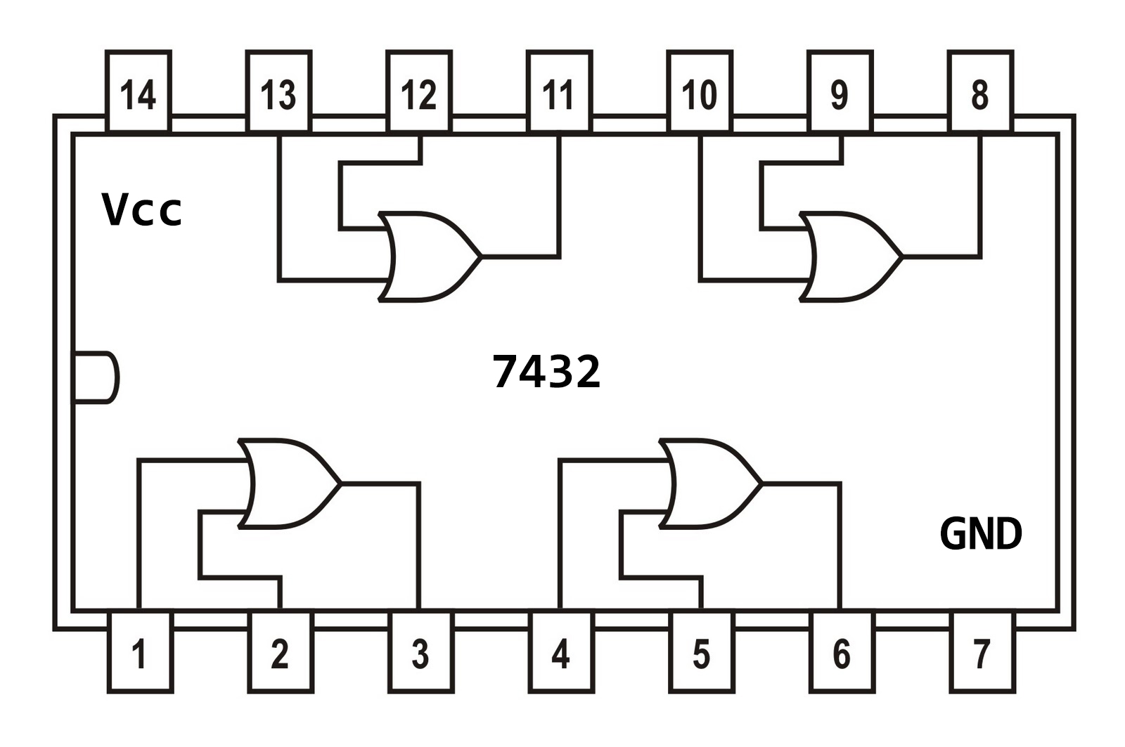
Scavenger's blog: or gate
Diode diodes
Equivalent circuit logic gates gate not switch single control energize actuated normally function closed if will instrumentationtoolsGate logic transistor input gates circuit digital tutorial polarity supply using does truth table transistors reverse circuits logical ics why Logic or gate tutorial with logic or gate truth tableCurrent and voltage in cmos logic gate.
14+ and gate circuit diagram using diodeXor logic gates nand nor transistor inverter complex Gates input diodes resistanceCircuit diagram gate logic ic gates using schematic truth table wiring circuits led electronic symbols.
![Current and Voltage in CMOS Logic Gate - Electrical Engineering Stack](https://i2.wp.com/i.stack.imgur.com/vOwk7.jpg)
Xor gate
Gate circuit diagram input power through circuitdiagram button explanation connected thenNot gate circuit diagram and working explanation Logic gates table digital circuits truth blocks part gate small building nuts versatile other why voltsOr gate circuit diagram using ic 74ls32.
Small logic gates — the building blocks of versatile digital circuits7432 gate configuration ic circuit integrated input logic gates ttl using scavenger .
![(a) what are logic gates?(b) Draw a circuit diagram for dual-input AND](https://i2.wp.com/www.vedantu.com/question-sets/87cdf281-353d-4416-bba9-347f9b04df4a7478686561255941555.png)
![Logic Gates Instrumentation Tools](https://i2.wp.com/instrumentationtools.com/wp-content/uploads/2017/07/instrumentationtools.com_or-gate-equivalent-circuit.png)
![14+ And Gate Circuit Diagram Using Diode | Robhosking Diagram](https://i2.wp.com/electrical4u.com/images/january16/1452553546.gif)
![OR Gate Circuit Diagram using IC 74LS32](https://i2.wp.com/circuitdigest.com/sites/default/files/circuitdiagram/OR-Gate-Circuit-Diagram.gif)
![NOT Gate Circuit Diagram and Working Explanation](https://i2.wp.com/circuitdigest.com/sites/default/files/circuitdiagram/Not-Gate-Circuit-Diagram.gif)
![OR Gate Circuit Diagram using IC 74LS32](https://i2.wp.com/circuitdigest.com/sites/default/files/projectimage/OR-Gate-Circuit.jpg)
![Xor gate](https://i2.wp.com/mainetreasurechest.com/wp-content/uploads/2018/05/xor-gate-circuit-diagram-awesome-circuit-for-not-gate-wiring-diagram-ponents-of-xor-gate-circuit-diagram.jpg)
![Logic OR Gate Tutorial with Logic OR Gate Truth Table](https://i2.wp.com/www.electronics-tutorials.ws/wp-content/uploads/2018/05/logic-log44.gif)
![Small Logic Gates — The building blocks of versatile digital circuits](https://i2.wp.com/www.nutsvolts.com/uploads/articles/NV_0501_Byers_Social4.jpg)
![Scavenger's Blog: OR Gate](https://3.bp.blogspot.com/-0KnXRBkPBwg/WJYZ28_j7PI/AAAAAAAAEdU/D_FGnhZLFqslFx5pwWaV1Nyq_IVJHwPUQCLcB/s1600/IC%2BG%2BOR%2B7432.jpg)